Second Order Low Pass Filter Circuit Diagram
Inductor passive Pass filter transfer wolfram order low active second community deriving equations language filters chose equation derive circuit shown diagram below Second order low pass filter(हिन्दी )
High Pass Filter: Definition, Circuit, Characteristics, and Applications
Topology for 1st order active low-pass filter Pass filter band circuit wide high low diagram bandpass which calculator segments normally intended dropping act different simple well Filter pass order low second
Filter pass active low order 1st circuit schematic topology circuitlab created using
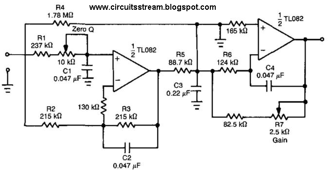
2nd order low pass filterAssumption current Low pass filter : circuit, types, calculators & its applicationsFilter pass high order second circuit characteristics diagram definition frequency cutoff active.
Passive low pass filtersHigh pass filter: definition, circuit, characteristics, and applications Low pass filter circuit diagramFilter circuit pass low diagram simple audio filters voltage passive basic ripple schematics nonlinear seekic gr next.

Filter low pass active order circuit second constructed
Pass filter low active circuit basic filters types amplifier schematic difference op amp lpf electronic between two order rc firstTransfer function The low-pass filter circuit of the second-order voltagecontrolledSolved the transfer function for the second order low-pass.
Low transfer function order pass second filter circuit given show solved figure transcribed problem text been hasSecond order low pass filter circuit the formula for phase calculation Lpf activeHigh order pass filter active second filters low frequency circuit nd resonances lecture capacitor ppt powerpoint presentation.

Simple low-pass filter circuit diagram
First order low-pass active filter: the circuit schematic diagram andCircuit filter diagram pass low First-order butterworth active low-pass filter circuitActive low pass filter.
Low pass filter : circuit, types, calculators & its applicationsDeriving transfer equations of active filters with wolfram language Pass circuit calculationPass circuit low rlc filter order passive filters first diagram wikipedia source circuits credit doeeet components fig tuned.

Filter pass low butterworth order active first circuit circuits tl081 high ic filters gain rf gr next
Op ampPassive engineer Pass filter order low passive 2nd frequency cutoff schematic function transfer circuit two filters electrical deriving consisting circuitlab created usingPrinted circuit board design techniques for emc compliance a handbook.
Band pass filter: circuit diagram, types, calculator and its applicationsFilter pass low order circuit diagram nd fig Lc low-pass filter questions.


Deriving transfer equations of active filters with Wolfram Language

Second Order Low Pass Filter(हिन्दी ) - YouTube

Topology for 1st order active low-pass filter - Electrical Engineering

Theory

current - Transfer function and weird assumption in circuit
Low Pass Filter Circuit Diagram
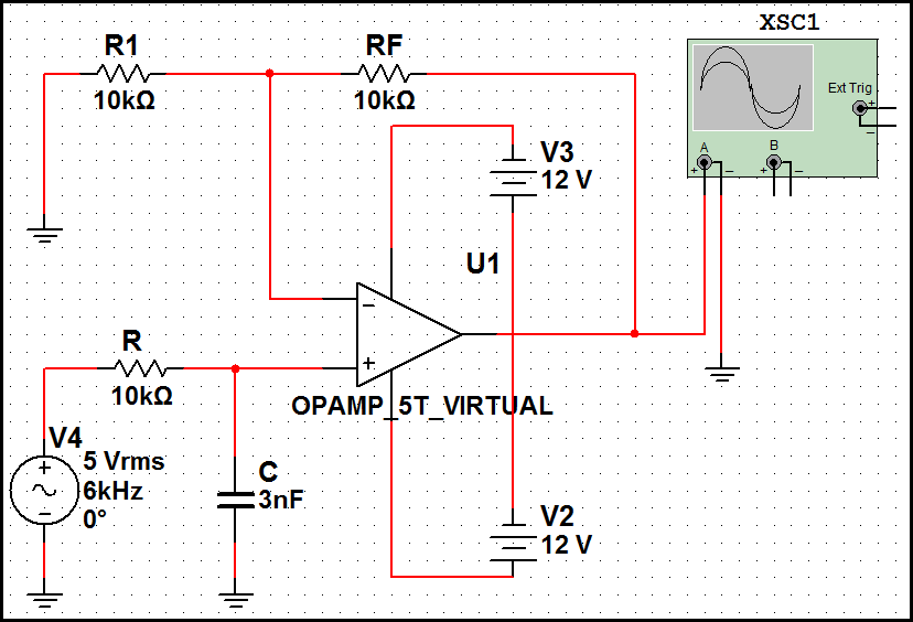
First-order butterworth active Low-pass filter circuit

Second order low pass filter circuit The formula for phase calculation