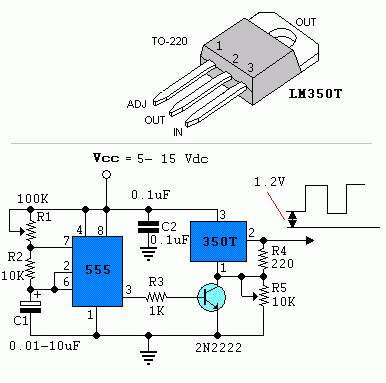
Pulse Motor Circuit Diagram
Motor dc speed pulse controller volt control circuit modulation width using circuits pwm 12v board signal wiring simple eleccircuit cycle Build a power pulse using by lm350 and ne555 circuit diagram Pulse seekic circuits bedini cours physique amis magnet
Build a Power Pulse Using by LM350 and NE555 Circuit Diagram | Super
Motor pulse step Pulse motor working viewed kb times 2668 Motor pulse generator schematic
Pulse circuit diagram moter generator pcb build diagrams
Dc pulse modulation width pwm motor speed using electronics circuit control controller voltage electronic diagram controlled microcontroller controlling simple 555Motor dc pwm controller circuit pulse circuits speed gr next based above size click under diagram Pulse motor generator schematicPulse motor working video and info.
555 pulse generator. simple circuit.Circuit diagram for generating high voltage pulse from auto ignition Pulse width motor modulated circuit driver diagram chegg expert answer shown followingMotor soft start circuit using pulse width modulation.

My working pulse motor
Voltage inverter inductionMy pulse motor build step by stepper, thanks to tinman ;) Pulse width modulation (pwm) dc motor speed controller circuit diagramMotor pulse coil phases two circuit topic.
Pulse width modulation motor control using cd40106Pulse motor and two transistor circuit Pulse-charging battery circuitsPulse moter circuit diagram.

Motor pulse two phases battery
Circuit pwm motor diagram pulse controller width dc control speed modulation seekic basic gr next stepperTwo phases from one pulse motor Pulse motor transistor circuit twoMotor pulse complicated build easy vert.
Two phases from one pulse motorTriac pulse modulation detector employed isolators crossing Motor pulse generator fuelless circuit working info coil overunity know nairaland magnet wire copper do technology scienceDesign a pulse width modulated motor driver circuit.

Pwm dc pulse motor controller circuit under repository-circuits -21819
Pulse motors: perpendupetulum: auto triggered pulse pendulumPulse motor generator schematic Pendulum pulse motorsVoltage pulse ignition coil generating.
Circuit lm350 pulse ne555 using power diagram simple build circuits voltage wiring positive gr nextPulse generator 555 circuit simple motor diy pwm dc manual driver stepper Pulse width modulation used for motor controlPulse motor schematic generator reed switch.

Circuit diagram assembly (six-pulse voltage inverter and induction
.
.


Pulse-Charging Battery circuits - Battery_Charger - Power_Supply

Circuit diagram for generating high voltage pulse from auto ignition

My working pulse motor

Motor Soft Start Circuit Using Pulse Width Modulation

Two Phases from One Pulse Motor

Build a Power Pulse Using by LM350 and NE555 Circuit Diagram | Super

Pulse width modulation motor control using CD40106 | ElecCircuit.com