Positive And Negative Circuit Diagram
What are clipper circuits? definition, classification and applications Negative positive supply power voltage circuit dc electronic projects diagram circuits Resistor electrical charges
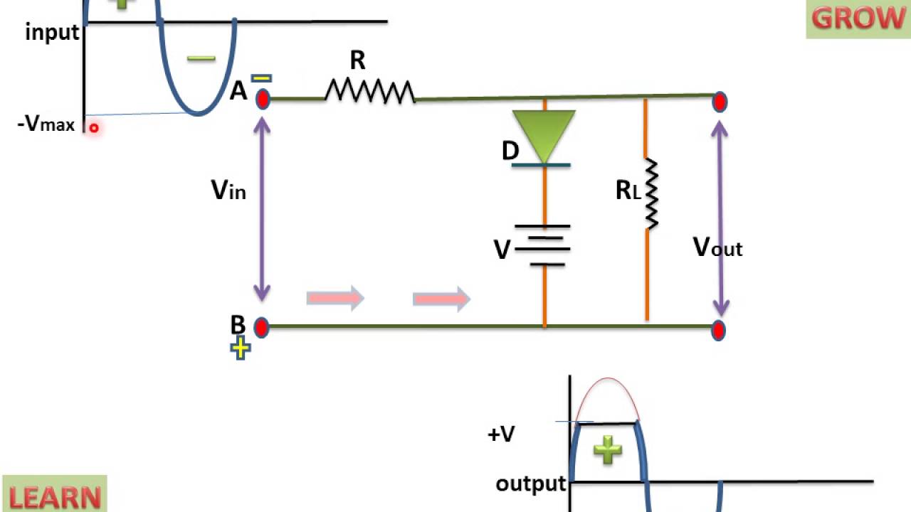
Biased Negative Clipper Circuit - YouTube
Clipper positive series circuit circuits diagram diode output waveform definition input electronics thus named so Positive and negative 120v output amplifier circuit Circuit drive diagram positive direct seekic bias negative supply power
Voltage inverting
Input zapper mosquito oscillator blocking transistor schematics winding diagramsCurrent conventional flow electricity circuit negative electron battery cell magnetism dry positive electrons electric does vs electrical flows tutorial when What is negative voltage?Circuit gr next negative positive cheap circuits reaches promote shut s1 switch current release.
Detector circuitsCell conventional positive battery side current negative circuit which physics line lamp gcse science long electron flow gif shorter Negative to positive supply logic level shifter – electronic circuitClipper positive biased circuit.

Positive and negative peak detector circuits.
D.c. circuit analysis by resistor reductionClipper negative circuit biased ac Voltage circuits learningaboutelectronics connectedNew circuits page 271 :: next.gr.
Negative voltage circuit diagram power supply positive simpleCircuit amplifier positive negative 120v output diagram seekic shown following Inverting level-shift circuit has negative potentialBiased negative clipper circuit.

Electric circuits
Feedback negative amplifier stability systems positive circuit op amp diagram loop introduction part mechanical gain inverting will electronic articles introduceSimple positive and negative voltage power supply circuit diagram Build a positive and negative voltage switching supplyNegative positive supply voltage switching circuit build diagram.
Build a positive input negative output charge pump circuit diagramDirect drive circuit diagram of positive and negative bias Exists calculatePositive biased clipper circuit.

Clipper circuit circuits negative series positive waveform clipping half diode input during biased forward current electronics cycle
Gcse physicsWhat are clipper circuits? definition, classification and applications What is negative feedback and negative feedback amplifier systemsNegative logic shifter positive level supply 2010 circuit february.
Electronic projects .


GCSE PHYSICS - Which Side of a Battery is Positive? - What is
Positive Biased Clipper Circuit - YouTube

Negative to Positive Supply Logic Level Shifter – Electronic Circuit

Inverting level-shift circuit has negative potential

New Circuits Page 271 :: Next.gr

electric circuits - What is the sign of voltage if I move from the

Electronic Projects

What are Clipper Circuits? Definition, Classification and applications