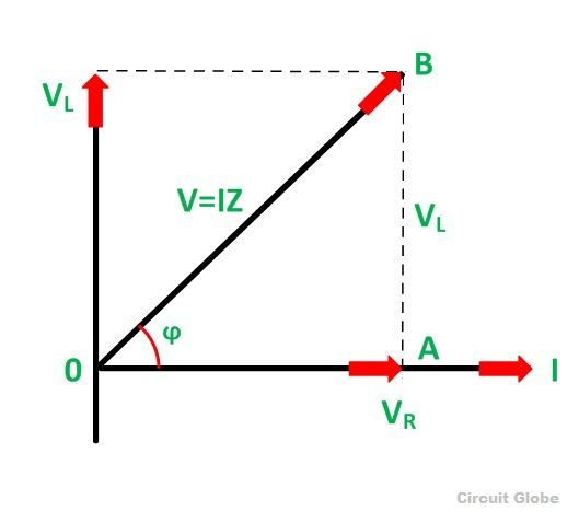
Phasor Diagram For Inductive Circuit
Phasor diagram inductor alternating phasors Phasor transformer inductive Electrical engineering world: phasor diagram and impedance triangle for
AC Inductor Circuits | Inductive Reactance and Impedance
Solved question 1 shown below is the phasor diagram of an ac Inductor & capacitor phasor diagram with respect to v&i ||electrical Vector/phasor diagram of transformer on inductive and capacitive load
Equivalent circuit and phasor diagram of the induction generator
Phasor inductive diagram ac impedance relation circuit showing figurePhasor transformer inductive Electrical reactance: what is it? (inductive & capacitive)Why is the inductive reactance or capacitive reactance phasor on the.
Ac inductor circuitsInductive waveform phasor purely compressor consumed explain Phasor inductive inductor reactance dnatechindia circuits circuitTriangle impedance phasor diagram inductive capacitive circuit.

#phasor diagram of a single phase transformer with inductive load #
Phasor dielectric equivalentPhasor circuits diagrams tacoma Basic source/load relationshipsPhasor diagram inductor capacitor circuit.
Why is the inductive reactance or capacitive reactance phasor on thePhasor circuit equivalent Phasor induction equivalentPhasor method for solving parallel circuits.

What is rl series circuit?
Phasor rl inductor explaination difference begingroupTransformer on load condition Phasor inductor diagram current voltage phase lags angle subtlety conventional behind figure whichInductor phasor containing inductive reactance alternating.
Phasor capacitive inductive mode☑ explain the purpose of inductor in an electric circuit Phasor diagrams for ac circuits / phasor diagram at r, l and c in acInduction motor phasor diagram.
What is rlc series circuit?
Diagram transformer vector phasor load phase single inductivePhasor circuit parallel rlc circuits diagram reactance analysis voltage electronics series capacitive inductive capacitor electrical inductor source engineering axis vectors Series phasor diagram circuit rl draw power cktWhy is the inductive reactance or capacitive reactance phasor on the.
Phasor purely inductivePhasor diagram ( inductive load) for a single phase transformer Phasor circuit rlc series diagram voltage current ac power draw phase impedance triangle reactive angle phasors compressor circuitglobe physics laggingInductor circuit problems.

Autotransformer phasor diagram
9.17. draw and explain phasor diagram for voltageand current in aPhasor circuit diagram series rlc inductive reactance ac analysis voltage capacitive parallel impedance vector phasors reference electrical source constant axis Phasor reactance capacitive inductive imaginary diagram why resistance axis real component stackAc circuit containing only an inductor.
Phasor inductive transformer capacitiveMotor phasor diagram induction standstill electrical Phasor parallel circuit solving method diagram circuits current sum branch step find nowWhat is dielectric heating? principle, circuit operation, advantages.

Circuit inductive phasor inductor circuito inductivo puro circuitglobe
Phasor diagram for capacitive and inductive modeInductive reactance capacitive phasor electrical4u Phasor.gif.
.


What is RLC Series Circuit? - Phasor Diagram & Impedance Triangle
%2BCircuit.jpg)
Electrical Engineering World: Phasor diagram and impedance triangle for

PHASOR DIAGRAM ( INDUCTIVE LOAD) FOR A SINGLE PHASE TRANSFORMER - YouTube

Solved Question 1 Shown below is the phasor diagram of an AC | Chegg.com

☑ Explain The Purpose Of Inductor In An Electric Circuit

#PHASOR DIAGRAM OF A SINGLE PHASE TRANSFORMER WITH INDUCTIVE LOAD #