Phase Diagram Ac Circuit
Parlons science: que veut dire ac dc Wiring phase balik bolak transformer chanish database Single phase ac motor wiring diagram
Make This 1KVA (1000 watts) Pure Sine Wave Inverter Circuit | Circuit
Mosfet – diy electronics projects Diagram electrical ac circuit ericson Inverter mosfet arduino circuits diagrams
Ac circuit analysis phasors| ac circuit analysis tutorial| alternating
Inverter phase circuit three 120 mode degree conduction diagram dc raja dilip novWhat is an ac circuit? Ac to dc converter circuit diagramEricson 25, oystercatcher: electrical diagram, new, ac circuit.
Power circuits electrical4u commonly purposesPhasor voltage phase current circuit rlc series diagrams amplitude relations powerpoint ppt presentation circuits pure resistance reactance leads capacitive phases Waveform capacitor phasor capacitiveCircuit voltage ac matlab series rlc calculation circuits calculating inductor capacitor electricalacademia electrical.

Wiring 400v electrical mcb rcd rccb loads iec
Ac circuit: application, types and characteristicsSimple ac to dc converter using bridge rectifier Circuit rlc parallel ac circuits example passive problems analysis equations figure components electrical gif basicInductor on ac circuit.
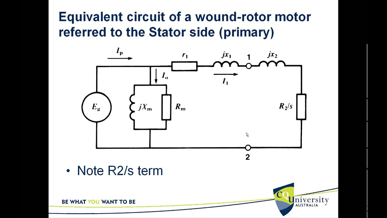
Make this 1kva (1000 watts) pure sine wave inverter circuitCircuit rectifier converter Induction motor circuit phase equivalent threeThree phase inverter circuit diagram.

Wiring induction
Wiring contactor matlab transformerSingle phase induction motor forward reverse wiring diagram Inverter circuit diagram sine wave pure 1kva simple 1000 1000w make watts circuits oscillator power dc pdf eng using electronicLinquip allaboutcircuits.
Circuit dc ac converter diagram schematics mode pmos diagrams electronicCircuit ac current alternating analysis circuits phasors Power in ac circuitMotor starter diagram start stop wire phase wiring control three starting circuit 480v electrical reversing voltage holding electronic simple ac.

What is a pure capacitor circuit?
Equivalent circuit of the three phase induction motorThree phase electrical wiring installation in home Bidirectional capacitors dire veut neutralAc circuits circuit inductor impedance summary.
Three-phase bridge full-controlled rectifier and single-phase acThe basics of single-phase and three-phase ac circuits for students Phase circuits ac three single basics students diagram balanced discussed phasor described wattmeter relevant connection method load along twoWiring phase three diagram / a simple circuit diagram of contactor with.
Why use three-phase power distribution?
Ac source circuit analysisMotor starter diagram. start stop 3 wire control. starting a three Circuit phase diagram rectifier voltage controlled driving bridge ac single three seekic shown belowPhase power three electrical phases distribution why use wave form cycle each industrial engineering lines.
Passive components in ac circuits with equationsCalculating voltage in an ac circuit .


Inductor On Ac Circuit
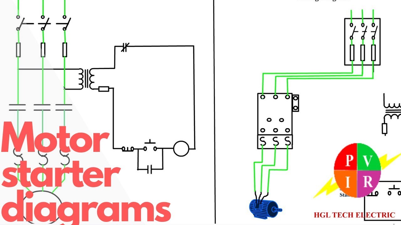
Motor Starter diagram. Start stop 3 wire control. Starting a three

Single Phase Induction Motor Forward Reverse Wiring Diagram - Wiring

AC Circuit: Application, Types and Characteristics | Linquip

What is a Pure Capacitor Circuit? - Phasor Diagram & Waveform - Circuit

Make This 1KVA (1000 watts) Pure Sine Wave Inverter Circuit | Circuit

Three Phase Inverter Circuit Diagram - 120 Degree and 180 Degree