Parallel Rc Circuit Phasor Diagram
Phasor diagram of parallel rc circuit Rc circuit parallel phasor diagram current vector phase impedance voltage figure between angle Phasor diagram circuit lrc
Solved Use the phasor diagram for a parallel R?L?C circuit | Chegg.com
What is rl series circuit? Rc circuit parallel ac circuits impedance diagram phasor equations components passive rl power examples basic electricalacademia Parallel rlc circuit and rlc parallel circuit analysis
Parallel rc circuit
Solved use the phasor diagram for a parallel r?l?c circuitCircuit parallel rc power impedance figure Parallel rc circuitPhasor circuit diagram series rlc reactance inductive ac analysis voltage capacitive parallel impedance vector phasors electrical reference source constant using.
Parallel rc circuit formula and phasor diagramPhasor diagram rl rc rlc circuits examples Circuit parallel rc impedance power figure question reviewCircuit rc phasor.

Resonance parallel diagram phasor circuit frequency condition current minimum component reactive draws under
Phasor diagram for lrc circuitParallel rc circuit Parallel rc circuitPhasor method for solving parallel circuits.
Series phasor diagram circuit rl draw power ckt belowPhasor diagram of rl, rc and rlc circuits (with examples) Parallel rc circuitPhasor diagram of parallel rlc circuit.
Phasor circuit rlc parallel diagram
Phasor circuit parallel rlc circuits diagram reactance analysis electronics voltage series capacitor inductive inductor source electrical capacitive ws tutorials vectorsPhasor circuit rlc series diagram voltage current ac power draw phase impedance triangle reactive angle phasors compressor circuitglobe physics lagging Circuit parallel rc impedanceParallel rc circuit.
Parallel circuit rc diagram phasor formulaPhasor parallel circuit solving method diagram circuits current sum branch step find now What is parallel resonance? effect of frequency & phasor diagramWhat is rlc series circuit?.
Why is the inductive reactance or capacitive reactance phasor on the
Phasor diagram parallel circuit current use figure following find part solved sourceCircuit rc parallel impedance Ac through series rl circuit : phasor diagramCircuit phasor diagram rl series ac.
.


Phasor Method for Solving Parallel Circuits - Circuit Globe

What is Parallel Resonance? Effect of Frequency & Phasor Diagram

What is RLC Series Circuit? - Phasor Diagram & Impedance Triangle

Why is the inductive reactance or capacitive reactance phasor on the

Phasor Diagram of Parallel RLC Circuit - YouTube

Parallel RC Circuit | Phasor Diagram | Impedance & Power | Examples
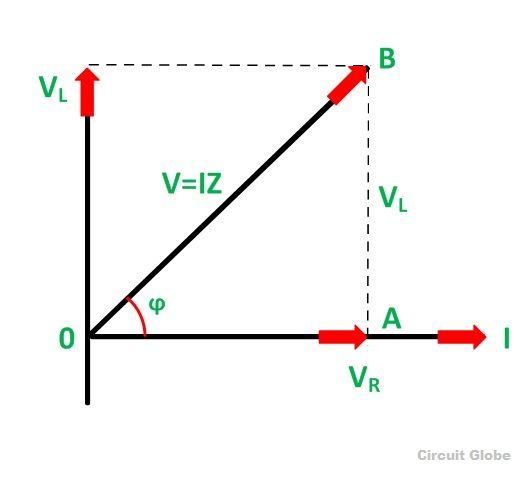
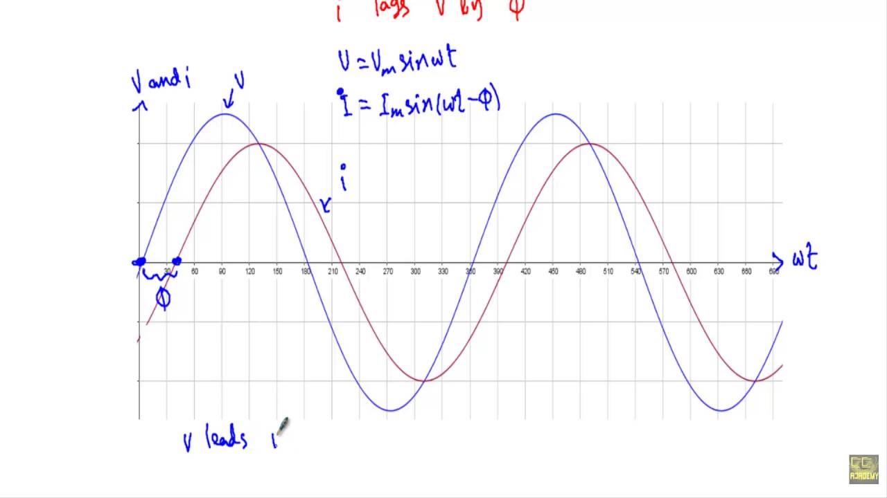
What is RL Series Circuit? - Phasor Diagram & Power Curve - Circuit Globe

Parallel RC Circuit | Phasor Diagram | Impedance & Power | Examples