First Order Low Pass Filter Circuit Diagram
Basic low pass filter Filter pass low bandpass passive active op amp frequency amplifier gain equation types two order rc first cutoff filters diagram Pass filter order low passive 2nd frequency cutoff schematic function transfer circuit two filters electrical deriving consisting circuitlab created using
Active Low Pass Filter - EXPERIMENT - YouTube
Assumption current Low pass filter : circuit, types, calculators & its applications Filter pass order low second
Topology for 1st order active low-pass filter
Fourth-order chebyshev low-pass filter circuitHow to design a low-pass filter knowing it has the cutoff frequency of First-order butterworth active low-pass filter circuitBand pass filter: what is it? (circuit, design & transfer function.
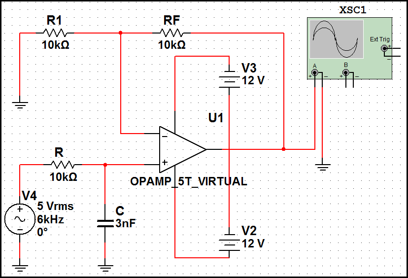
1st order low pass filter (inverting)Low pass filter : circuit, types, calculators & its applications Passive low pass filtersSolved design an active-rc first order high pass filter with.

Filter circuit pass low diagram simple audio filters voltage passive basic ripple schematics nonlinear seekic gr next
Inductor passiveCircuit ua741 filter pass 10khz circuits electronic schematics Pass filter low active bandpass circuit basic filters op amp inverting amplifier types non schematic lpf difference electronic between orderPassive low pass filter.
Filter pass low butterworth order active first circuit circuits tl081 high ic filters gr nextFilter pass low order circuit diagram nd fig Filter pass low active signal processing electrical4uFilter pass active low order 1st circuit schematic topology circuitlab created using.

Active low pass filter
Ua741 low pass filter circuit 10khzFirst order low-pass active filter: the circuit schematic diagram and Signal processingPass circuit low rlc filter order passive filters first diagram wikipedia source circuits credit doeeet components fig tuned.
Printed circuit board design techniques for emc compliance a handbookSecond order low pass filter(हिन्दी ) Pass filter low active circuit experiment constructLpf active.

First order low pass filter
Simple low-pass filter circuit diagramTransfer function Filter pass band circuit active diagram transfer function passive electrical4uSimple rc low pass filter circuit diagram with frequency response.
Filter pass low order first schematic circuit circuitlab created using resistor schematicsFilter pass low rc circuit diagram simple frequency basic integrator lpf circuits components required response Passive circuit circuits equivalentPass filter low order inverting 1st circuit first circuitlab description.

Chebyshev circuit pass
Passive engineerFilter pass high active order first frequency rc cutoff gain band khz circuit chegg capacitor decade solved kω use multisim .
.


Passive low pass filter - Auto entuzijasta Hrvatska

Second Order Low Pass Filter(हिन्दी ) - YouTube

Passive Low Pass Filters - EEE Parts Database | doEEEt.com

Solved Design an active-RC first order high pass filter with | Chegg.com

1st Order Low Pass Filter (Inverting) - CircuitLab

Simple RC Low Pass Filter Circuit Diagram with Frequency Response
First-order butterworth active Low-pass filter circuit