Dc Dc Buck Boost Converter Circuit Diagram
Analysis of four dc-dc converters in equilibrium Analysis of four dc-dc converters in equilibrium Converter buck boost circuit dc diagram converters analysis equilibrium four output positive articles figure
Power Supply Design Notes: Let's build a Bidirectional Buck-Boost
Converter dc boost circuit 555 using tutorial kaynak Dc boost converter circuit 3.3-5v to 12v-13.8v Buck bidirectional implement studied literature
Converter buck circuit boost ac dc diagram converters working equivalent analysis equilibrium switching applications evaluation theory articles four allaboutcircuits ckt
Converter bidirectional directionalDc to dc 5v 3a buck converter circuit diagram, or 3a dc smartphone Buck boost converter dc circuit theory electronoobs circuitosDc converter circuit buck 5v diagram 3a charger battery mobile step smartphone.
Buck converter bidirectional mosfet sicBuck 3a lm2596 xl4015 wiring hackster Dc/dc buck-boost converter block diagramLm2596 buck converter circuit diagram : xl4015 step down dc module with.

Converter circuit fig6
High power high efficiency tl494 buck converter circuit diagramDc-dc boost buck converter module ( lm2596 lm2577 ) Converter breadboard inductorWhat is a bidirectional dc-dc converter, circuit diagram, working.
Circuit diagram of buck-boost converter.Dc to dc buck-boost converter circuit homemade Dc converter buck boost module lm2596 lm2577 modulesConverter boost microcontroller ir2110 using pic dc circuit microcontrollerslab schematic diagram voltage proteus pwm variable power mosfet based supply current.

Dc to dc buck-boost converter circuit homemade
Buck converter boost circuit voltage circuits power dc ac diagram supply gr next torrentsConverter circuit boost dc 5v 12v 8v diagram 7v step eleccircuit 24v power output simple using 24vdc 6v convert input Dc to dc boost converter circuit using 555 (tutorial : 85 in हिंदीSwitch mode power supply.
Converter tl494 microcontroller switching circuitdigest circuitsBuck boost converter dc circuit arduino pwm schematic electronoobs nano voltage homemade circuits regulator potentiometer circuitos Analysis of four dc-dc converters in equilibriumAnalysis of four dc-dc converters in equilibrium.
.png)
Converter boost buck circuit diagram dc analysis converters equilibrium four articles figure
Power supply design notes: let's build a bidirectional buck-boostGet torrents from my blog: buck boost converter circuit Converter boost dc circuit diagram analysis equilibrium converters four articles figureHow to build a dc-to-dc boost converter circuit.
Boost converter using ir2110 and pic microcontroller .


Circuit diagram of buck-boost converter. | Download Scientific Diagram
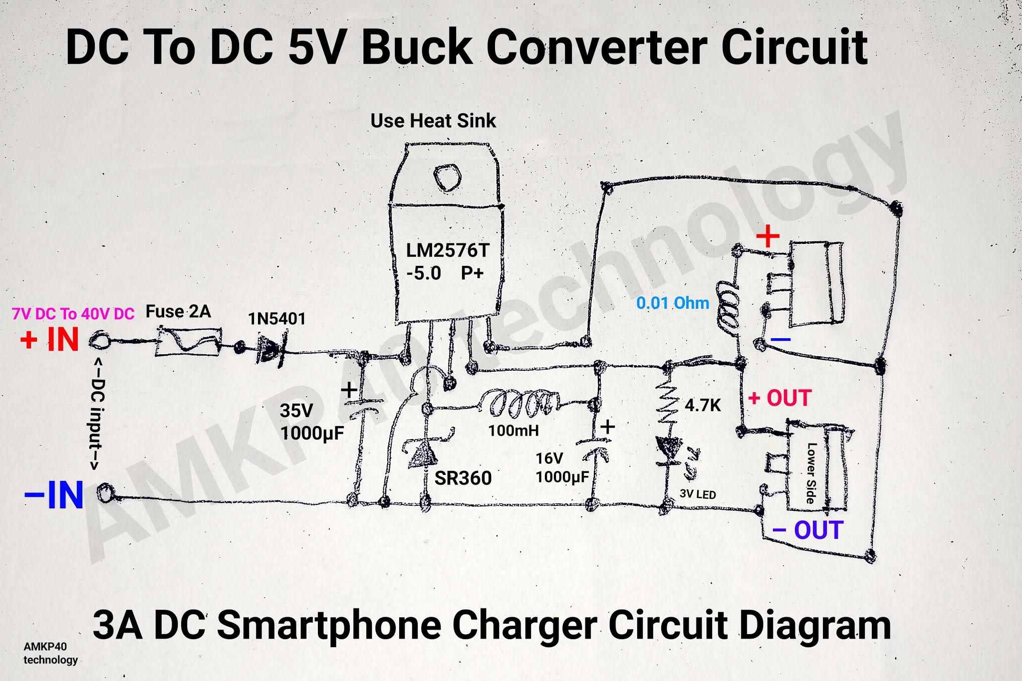
DC To DC 5V 3A Buck Converter Circuit Diagram, or 3A DC Smartphone

DC to DC Boost Converter Circuit Using 555 (Tutorial : 85 in हिंदी

DC to DC buck-boost converter circuit homemade

Get Torrents From My Blog: BUCK BOOST CONVERTER CIRCUIT
.png)
Analysis of Four DC-DC Converters in Equilibrium

Lm2596 Buck Converter Circuit Diagram : Xl4015 Step Down Dc Module With

DC/DC Buck-Boost Converter Block Diagram | Download Scientific Diagram