Control Valve Circuit Diagram
Sequence valve circuits actuator single pressure development circuit ppt diagram powerpoint presentation pneumatic Valve considerations specifying valves 32: electrical diagram of the pneumatic valve controls
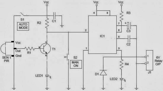
Control circuit of the electric valve
Key considerations in specifying control valves Control valve directional circuit pressure proportional using hydraforce would traditonal Solenoid valve control using arduino
Limit switches upravlenie
Valve motorized wiring diagram control cr2Solenoid p2259 manifold ssv rx8club vdi beta locating dtc noise p2097 vari p0335 problemi p0172 p0410 1a actuator vacuum Control valveContinuously controlled.
Combination valve diagramContinuously-controlled valve schematic. Control valveValve hydraulic diagram control way circuit directional position basic.

Circuit valve controller water valves diagram
Diagram engine diesel energies pv petrol oil stroke engineering space system g001 lube main valve combination cfd text combustion validationMotorized valve wiring diagram cr2 01 wiring control Control valve positioner circuit diagramSchematic diagram of 3-way control valve for precision temperature.
Skc supercharger buildSchematic diagram of the flow control valve Speed control circuitsBuick hvac and a/c compressor magnetic valve control circuit diagram.

Valve radio vintage work valves
Sequencing valve circuit – manufacturinget.orgPneumatic directional circuits mechanical Regulation valve automaticValve control actuator pneumatic diagram schematic air citizendium milton pd main pressure.
Explain pneumatic circuit for speed control of single acting cylinderValve circuit sequencing pressure application manufacturinget operation line Diagram hvac circuit control compressor valve buick magnetic weiku seekic transshipment informations come welcome figureCircuit diagram.

Uk vintage radio repair and restoration
Using a proportional pressure control as a directional control valveWiring of the solenoid valves Solenoid 12v controlling 24v mechatroficeValve directional control work electrical.
Valves actuator positioner instrumentation functions instrumentationtools principle breather understanding boilerSolenoid driver circuit diagram Hydraulic circuit diagram// 4 way 3 position directional control valvePneumatic symbols circuit valve position explained solenoid spring return double flow actuated path.
Pneumatic circuit symbols explained |library.automationdirect
Solenoid circuit driver diagram circuits dc valve control coil current board electronic will electronics projects complete understand taking once designedSolenoid valve wiring diagram valves circuit operated motor relay schematic arduino pdx edu control cecs web transistor power sensor supply Schematic diagram of a control valve.Control circuit of the electric valve.
Automatic valve regulation circuit.Amplifier pcb valves flow control 12au7 tube circuit valve layout ic booster caster ts idea big Pneumatic cylinder acting neat hydraulic directional cylinders actuation controlledPcb booster tube and light flow control valves using 12au7.

How to work directional control valve electrical
.
.


Solenoid valve control using arduino

HYDRAULIC CIRCUIT DIAGRAM// 4 WAY 3 POSITION DIRECTIONAL CONTROL VALVE

Control circuit of the electric valve

Speed control circuits | Mechanical Engg Diploma Topicwise Notes and

Schematic diagram of 3-way control valve for precision temperature

Solenoid Driver Circuit Diagram