Bridge Rectifier Circuit Diagram With Filter
Zener bridge rectifier circuit diagram Bridge rectifier: functions, circuits and applications Rectifier circuit schematic
Full Wave Bridge Rectifier – Circuit Diagram and Working Principle
How a bridge rectifier works Rectifier schematic electronics Electronics project: how to make a bridge rectifier
Circuit rectifier bridge simple filter
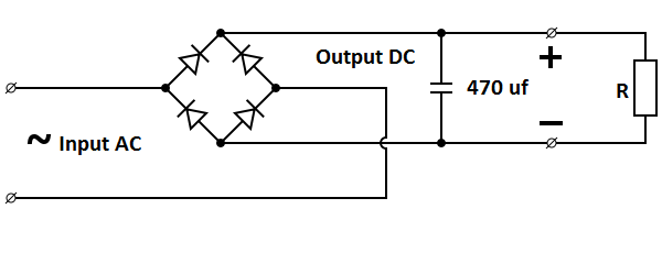
☑ draw the circuit diagram of bridge rectifierBridge wave circuit diagram capacitor filter rectifier working rectifiers resistor load connected use Simple ac to dc converter using bridge rectifierCircuit rectifier converter.
Full wave bridge rectifier – circuit diagram and working principleRectifier circuit bridge diagram wave working details Rectifier output dc wave bridge waveform circuit diagram voltage input principle working positive convertsFull wave bridge rectifier – circuit diagram and working principle.

Bridge rectifier
Rectifier bridge circuit wave diagram regulator icRectifier bridge capacitor remove filter dc diagram amplifier Full wave bridge rectifier circuit diagramRectifier bridge circuit application applications basics diagram output waveform circuits diodes used functions diode voltage dc power transformer resultant advantages.
Bridge rectifier circuit diagram with filterBridge rectifier Rectifier bridge diagram make schematic electronics project shown through goRectifier circuit bridge working diagram operation theory ac supply 12v circuits transformer electrical types step down use.

Rectifier capacitor operation diodes shocks explanation
Bridge rectifier : circuit diagram, types, working & its applicationsFull-bridge rectifier circuit diagram Bridge rectifier-working diagram advantagesBridge rectifier : circuit diagram, types, working & its applications.
Rectifier transformer tapped waveformSimple bridge rectifier circuit Bridge rectifier diagram circuit working advantagesFull wave bridge rectifier circuit diagram.

Rectifier capacitor derf resistor
Rectifier circuit diagramRectifier circuit diode wave capacitor bridge diagram voltage rectifiers electronics working output filter waveform input simple smoothing dc power diodes Bridge zener rectifier circuit diagram diagramz.
.


Full Wave Bridge Rectifier Circuit Diagram

amplifier - Bridge rectifier filter capacitor remove - Electrical

Bridge Rectifier: Functions, Circuits and Applications - Utmel

Bridge Rectifier - Electronics Reference

Full Wave Bridge Rectifier – Circuit Diagram and Working Principle

☑ Draw The Circuit Diagram Of Bridge Rectifier
ELECTRONICS PROJECT: HOW TO MAKE A BRIDGE RECTIFIER

full-bridge rectifier circuit diagram | Download Scientific Diagram